Topics on this page
Choose a deployment option
Network Security is offered as an Amazon Machine Image (AMI). When you decide how to deploy Network Security in your network, we recommend that you choose one of the following deployment options.
Network Security virtual appliances do not support auto-scaling.
Each deployment option is a reference architecture created for different common AWS environments. Choose the option that best suits your existing network structure and inspection needs. These deployment recommendations can also be modified to suit the individual requirements for your network.
The arrows in the images indicate the flow of network traffic through the VPCs and the Network Security instance.
Inspect inbound internet traffic
The following deployment options are best suited for environments that need to inspect traffic that flows into the VPC from the internet gateway.
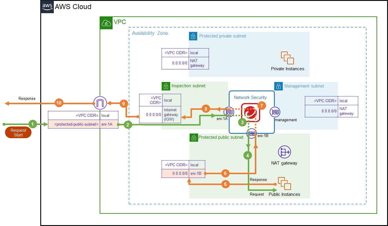
Option 1: Edge protection deployment (recommended): This deployment protects servers that primarily receive connections from the internet. Deployment checklist.
Deploy this option automatically using the Deploy Protection wizard on the Network Security management interface.
This deployment option is best suited to environments that require the following:
- A simple network design that protects web servers.
- Deployment of multiple virtual appliances.
- Inspection between the VPC and the Internet as well as between the VPC and a VPN gateway.
- A single VPC — this deployment option does not require Transit Gateways.
- Third party appliance integration that follows AWS best practices.
This deployment option does not indicate an IP address for the true source instance when a NAT Gateway is used for outbound internet traffic.
Refer to the image below for details on the environment structure and routing for this deployment. The numbered arrows represent the order of the flow of traffic through the environment. Green represents the request and orange represents the response.
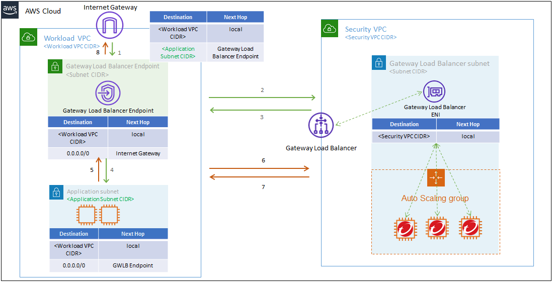
**Dynamic auto-scaling is not yet supported for Gateway Load Balancer in Network Security. **
Option 2: Deploy a centralized virtual appliance with Gateway Load Balancer for inbound traffic: This deployment protects servers that primarily receive connections from the internet.
This deployment option is best suited to environments that require the following:
- An environment that requires centralized security inspection for multiple VPCs across different AWS accounts.
- An environment that includes one or multiple Workload VPCs.
- A separate VPC (referred to as the Security VPC in the image below) where the Network Security virtual appliance and the Gateway Load Balancer are located.
- Traffic that flows through the Gateway Load Balancer VPC endpoint, located in a Workload VPC, without leaving the AWS network.
Refer to the image below for details on the environment structure and routing for this deployment. The numbered arrows represent the order of the flow of traffic through the environment. Green represents the request and orange represents the response.
Inspect outbound internet traffic and lateral traffic
The following deployment options are best suited for environments that need to inspect traffic that flows out of the public VPC through the internet gateway and/or to inspect east to west traffic flows between VPCs within your environment.
**Dynamic auto-scaling is not yet supported for Gateway Load Balancer in Network Security. **
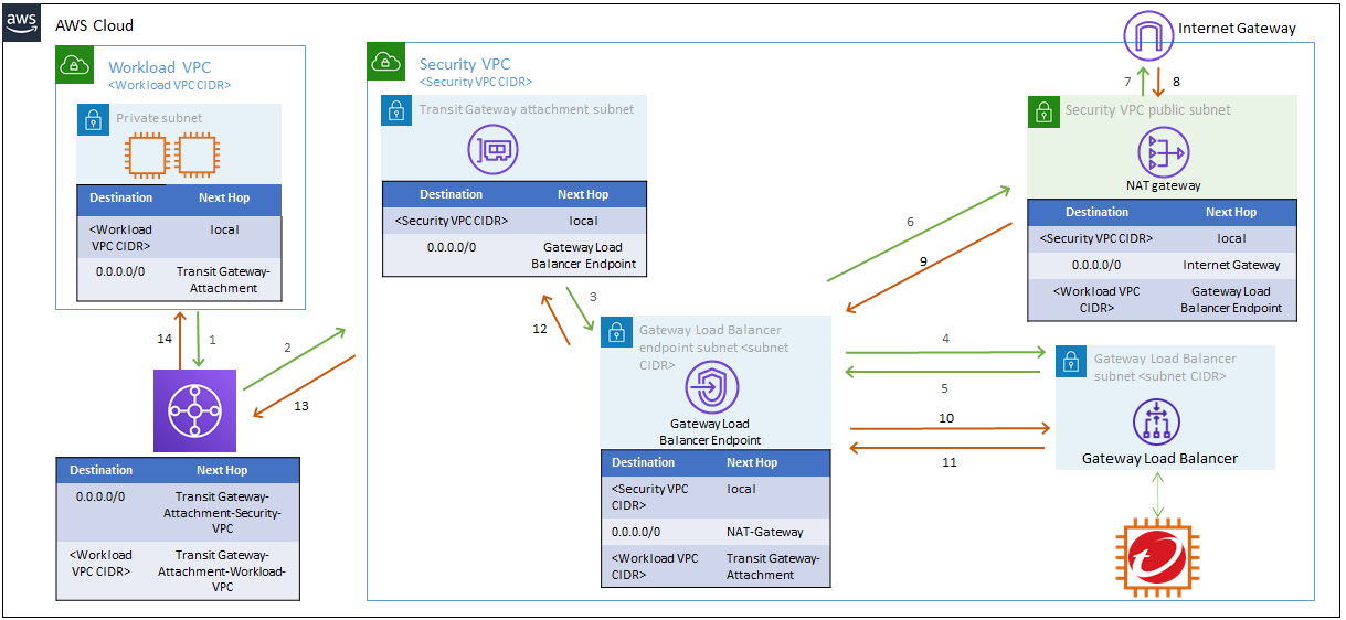
Option 3: Deploy a centralized virtual appliance with Gateway Load Balancer for outbound or lateral traffic: This deployment is designed for AWS architectures that primarily send traffic from EC2 instances to the internet and/or between EC2 instances in different Workload VPCs.
This deployment option is best suited to environments that require the following:
- More than one Workload VPC that needs protection at the same time by a centralized Security VPC.
- Environments that use Transit Gateways.
This topology does not inspect inbound connections.
Refer to the image below for details on the environment structure and routing for this deployment. The numbered arrows represent the order of the flow of traffic through the environment. Green represents the request and orange represents the response.