Topics on this page
Inspect inbound and outbound traffic with Azure Firewall
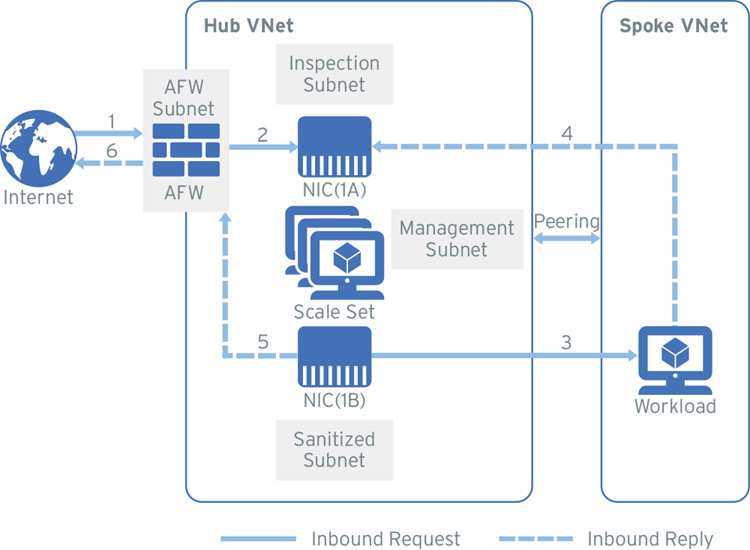
This deployment option describes how to deploy a scale set of virtual appliances behind the Azure Firewall to provide advanced network protection. Deploying a scale set behind the Azure Load Balancer provides additional layers of availability, which means minimal disruption if a virtual appliance experiences an outage.
The following diagram shows an example of the traffic flow for this deployment:
IMPORTANT: Internet connectivity notice
During the Deploy the Network Security virtual appliance step, the Network Security virtual appliance is configured behind a standard internal load balancer. The placement of this load balancer blocks the outbound internet connectivity by default unless internet connectivity has been explicitly declared. For this deployment, add a NAT gateway to the management subnet to allow outbound connectivity so that your Network Security virtual appliance can communicate with Network Security. This option is configured before the Network Security virtual appliance is deployed.
Complete these tasks to set up your environment:
- Create a resource group
- Create spoke virtual network and subnets
- Create hub virtual network and subnets
- Add peering to connect the hub and spoke-VNets
- Add a NAT gateway to the management subnet
- Deploy the Network Security virtual appliance
- Configure the firewall
- Configure route tables
Before you begin
- Review Azure's naming conventions.
- Set up Azure Monitor. Write down the Log Monitor Workspace ID and Log Monitor Primary Key.
- Generate a Trend Micro Cloud One appliance deployment token.
Create a resource group
Create a resource group if one does not already exist in your environment.
- Navigate to Resource groups → + Add.
- Select your subscription, name the resource group, then select a region.
- Click Review + Create.
Create the spoke virtual network and workload subnet
- Navigate to Virtual Networks → + Add.
- Enter values for the fields in the Basics tab, naming the instance
Spoke-VNet. - In the IP Address tab, edit the IPv4 address space and enter a new address.
- Click + Add Subnet and enter these details:
- Subnet name:
Workload1-Subnet - Subnet CIDR (example): 10.1.1.x/x
- Subnet name:
- Click OK.
- Skip the Security and Tags tabs.
- Click Review + Create, and then click Create.
Create a Workload virtual machine (optional)
Follow these steps if you are creating this environment as a proof of concept or if you do not have an existing workload in your environment.
- Navigate to Virtual machines → + Add → Virtual machine.
- In the Basics tab, fill in the required fields. Enter the following for the Name and Inbound port rules:
- Name:
WorkloadVM - Public inbound ports: None
- Name:
- In the Disks tab, select Standard HDD for the OS disk type and configure the other settings.
- In the Networking tab, enter these values:
- Virtual network:
<Your Spoke-VNet> - Subnet:
WorkloadSubnet - Public inbound ports: None
- Virtual network:
- Fill in the information in the remaining tabs.
- Click Review + Create, and then click Create.
- Write down the Private IP address after the deployment is complete.
Backend workloads example
If you followed the steps above to create a workload in your Azure environment, the following table provides an example of configuration details for two virtual machine web workloads. Install an HTTP server if you intend to configure backend workloads after they are created.
| Network interface | Subnet | IP example |
|---|---|---|
| WorkloadVM1 | WorkloadSubnet1 | 10.3.x.x |
| WorkloadVM2 | WorkloadSubnet2 | 10.4.x.x |
Create the hub inspection virtual network and subnets
Use the procedure below to manually set up the inspection-VNet (hub) and subnets. You will select all of the subnets when you deploy your Network Security virtual appliance.
-
Navigate to Virtual Networks → + Add.
-
Enter values for the fields in the Basics tab, naming the instance
Hub-VNet. -
In the IP Address tab, edit the IPv4 address space and enter a CIDR.
-
Click + Add Subnet and enter the following information to create four subnets:
Subnet name Subnet CIDR examples Management-subnet10.0.0.x/x Inspection-subnet10.0.1.x/x Sanitized-subnet10.0.2.x/x Loadbalancer-subnet10.0.3.x/x
NOTE
The internal load balancer (ILB) is created when you deploy your Network Security virtual appliance from Azure Marketplace.
-
Skip this step if you already have an Azure Firewall or a third party firewall set up.
In the Security tab, select Enable for the Firewall setting and fill in the firewall details.- Firewall name:
AzureFirewall - Firewall subnet CIDR (example): 10.0.100.x/x
- Public IP address: Click Create New → add an IP address, select Regional or Global, then click OK.
- Firewall name:
-
Click Review + Create, and then click Create.
Add peering to connect the hub and spoke VNets
- Navigate to the Virtual networks page.
- Click Spoke-VNet → Peerings → + Add.
- The peering connection is from the Spoke-VNet to the inspection VNet. Enter the following configuration details, then click Ok.
- Peering connection name:
Spoke-to-Hub - Virtual network deployment model: Resource manager
- Subscription: Your subscription
- Virtual network:
<your Spoke VNet> - Peering connection name:
Hub-to-Spoke - Allow virtual network access from Hub-VNet to Spoke-VNet: Enabled
- Allow virtual network access from Spoke-VNet to Hub_VNet: Enabled
- Allow forwarded traffic from Spoke-to-Hub: Enabled
- Allow virtual network access from Hub-to-Spoke: Enabled
- Allow gateway transit: Disable
- Peering connection name:
Add a NAT gateway to the management subnet
As described in the Internet connectivity notice section, add a NAT gateway associated with the management subnet to your configuration to allow the Network Security virtual appliance to communicate with Network Security.
NOTE
There is an option to automatically generate a NAT gateway when you deploy the Network Security virtual appliance. Select the option to automatically generate the NAT gateway in the Deploy the Network Security virtual appliance section or use these steps to manually deploy the NAT gateway.
- Navigate to NAT gateways → + Add.
- Enter the required information on the Basics tab.
- In the Outbound IP tab, select Public IP addresses or Public IP prefixes depending on your resources.
- Public IP address: A single IP address
- Public IP prefixes: A range of public IP addresses
- In the Subnet tab, select your Hub-VNet name, then select the management-subnet.
- Click Review + Create, and then click Create.
The management subnet can be associated after the NAT gateway is created by clicking the Subnet menu option from the NAT gateway details page.
Deploy the Network Security virtual appliance
The Network Security virtual appliance is available from the Azure Marketplace as a public offer. To deploy the Network Security virtual appliance, navigate to Azure Portal → Marketplace → Trend Micro Cloud One™ – Network Security.
Manually add virtual appliances to Trend Micro Cloud One if the Azure Marketplace deployment does not properly register the virtual appliance(s) to Network Security.
Gather the following information before you begin the deployment:
- The VNet resource group name.
- Names of the management, inspection (Dataporta), sanitized (Dataportb), and load balancer subnets.
- Your Trend Micro Cloud One appliance deployment token
- The Log Analytics workspace ID and Primary Key: Register your Log Analytics workspace during the deployment process so that your logs will be sent to the Network Security management interface.
Note
Best practice is to copy and paste the exact names of the resource group, hub-VNet, and subnets.
- Log into Azure and select Create a resource (this will direct you to the Marketplace).
- Search for Trend Micro Network Security.
- Next to Select a plan, choose Scale Set VM in the dropdown menu.
- Click Create.
- Enter the following information in the Basics tab:
- Enter your Trend Micro Cloud One appliance deployment token
- If selected, create a public user key (SSH key).
- Select the following information in the Networking tab:
- Your virtual network.
- All of the subnets you created in the inspection-VNet.
- For NAT Gateway, either choose Create new to automatically create a new NAT gateway when you deploy the virtual appliance, or choose Select existing if you already manually created a NAT gateway.
- Enter or select the following information in the Advanced tab:
- (Suggested) Keep the Boot diagnostics setting enabled.
- Select your boot diagnostic account, or create a new one.
- Enter the Log Analytics workspace ID and Primary Key in order to upload your logs to the Network Security management portal.
- Click Review + Create, and then click Deploy.
Configure the Azure Firewall
After you create and deploy the Azure Firewall, make the following configuration changes. Learn more.
Note the Firewall IP information
Private and public IPs are assigned automatically after you create the firewall. Note the IP information for future use in the deployment process.
- Navigate to Firewalls → AzureFirewall.
- Select Public IP Configuration.
- Write down the Private and Public IP addresses for the AzureFirewallSubnet.
Configure the Firewall rules
Configure the AzureFirewall NAT Rule (Ingress) and Network Rule (Egress).
Configure the NAT rule
- Navigate to Firewalls → AzureFirewall.
- Select Rules → NAT rule collection tab.
- Click + Add NAT rule collection.
- Enter a name and priority.
- Configure the NAT rule settings:
- Name:
Ingress - Protocol: TCP
- Source type: IP address
- Source:
* - Destination address:
<Public IP of the AzureFirewall> - Destination ports:
80 - Translated address:
<Private IP of your Workload VM> - Translated port:
80
- Name:
- Click Add.
Configure the Network Rule
- Navigate to the Network rule collection tab and click + Add network rule collection.
- Add a name, priority, and action.
- Configure the NAT rule settings:
- Name:
Egress - Protocol: Any
- Source type: IP address
- Source:
Your entire V-Net - Destination type: IP address
- Destination address:
* - Destination ports:
*
- Name:
- Click Add.
Configure route tables and rules
After the Network Security virtual appliance is deployed, add and configure the route tables and routes to place your virtual appliance in-line and begin inspecting traffic. The firewall rules are applied to the network traffic when it is routed to the firewall as the subnet default gateway.
The following information is required to complete this process:
- Inspection subnet private IP
- Sanitized subnet private IP
- AzureFirewall private IP
- AzureFirewallSubnet CIDR
- Spoke-VNet CIDR
Step 1: Create three route tables
- Navigate to Route tables and click + Add.
- Enter these values for each route table:
- Table one:
Firewall-rt - Table two:
DataportB-rt - Table three:
Spoke-rt
- Table one:
- Click Review + Create, and then click Create.
- Repeat this process for the remaining tables.
Step 2: Configure the route tables
- From the Route tables page, select the Firewall-rt table, then click Routes → + Add.
- Enter this information:
- Name:
toSpoke - Address prefix:
<CIDR of the Spoke-VNet> - Next hop type:
Virtual Appliance - Next hop address:
<IP address of the internal load balancer> - Click OK.
- Name:
- Add another route to the Firewall-rt.
- Name:
Default - Address prefix:
0.0.0.0/0 - Next hop type:
Internet - Click OK.
- Name:
- Select the DataportB-rt table, then click Routes → + Add.
- Name:
Default - Address prefix:
0.0.0.0/0 - Next hop:
Virtual Appliance - Next hop address:
<Private IP of AzureFirewall> - Click OK.
- Name:
- Select the Spoke-rt table, then click Routes → + Add.
- Enter this information:
- Name:
toSpoke - Address prefix:
<CIDR of the Spoke-VNet> - Next hop type:
Virtual Appliance - Next hop address:
<IP address of the internal load balancer> - Click OK.
- Name:
- Add another route to the Spoke-rt table.
- Name:
toFirewall - Address prefix:
<CIDR of AzureFirewallSubnet> - Next hop:
Virtual Appliance - Next hop address:
<IP address of the internal load balancer> - Click OK.
- Name:
- Add another route to the Spoke-rt table.
- Name:
Default - Address prefix:
0.0.0.0/0 - Next hop:
Virtual Appliance - Next hop address:
`<IP address of the internal load balancer> - Click OK.
- Name:
Step 3: Associate the route tables to the related subnet
- Select your Spoke-rt table, then click Subnets → + Associate.
- Virtual network:
Spoke-VNet - Subnet:
Workload1-subnet
- Virtual network:
- Select your Firewall-rt table, then click Subnets → + Associate.
- Virtual network:
<Your Hub-VNet> - Subnet:
<AzureFirewallSubnet>
- Virtual network:
- Select your DataportB-rt table, then click Subnets → + Associate.
- Virtual network:
<Your Hub-VNet> - Subnet:
<Sanitized-hub>
- Virtual network: